A Comprehensive Guide For Understanding The SMPS Power Supply
What is Switch-mode Power Supply (SMPS)?
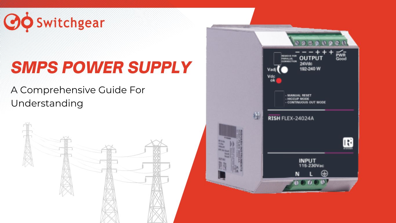
SMPS (Switched-mode power supply), also called switch mode power supply units, have become the primary efficient power conversion source that takes a mains voltage AC input and converts it down to a low voltage DC output, just like we have read about it in the step-down transformers. AC-DC switched-mode converters are omnipresent; the external desktop power supply for your laptop, inside your set-top box, and the wall plug-in charger for your smartphone. The SMPS 24Vdc supply unit Din Rail with 10Amp primary switch (from switchgear) is a major product from the category that can efficiently convert AC supply to DC for home devices.
In the past, the linear method of power conversion was used to convert AC to DC. Linear power supplies typically required heavy or bulky transformers with analog “linear’ regulation circuitry. Transformers generate large amounts of waste heat dissipation, due to average conversion efficiencies of less than 65%.
Compared to an analog linear system, switched-mode power supplies are compact, power-efficient, usually have more than 85% conversion efficiency, and lightweight. Switched-mode power supplies are also highly flexible from a design perspective, enabling designers to find an optimal solution for their end product’s power requirements. The Switched Mode Power Supply Unit SMPS 24Vdc 2.5A 1Phase DIN Rail – RISH_Flex-E_6024A from the GoSwitchgear has an output rated power of 150%.
Switched-mode principles
The principles of switched-mode conversion apply to both AC-DC and DC-DC power supplies. An AC-DC power supply involves a series of stages, including rectifying a single-phase 230Vac or 3-phase 400Vac 50Hz mains voltage, before the DC-DC conversion stages.
In both cases, in the DC-DC conversion stage, a primary circuit of power semiconductors, which is a power switch circuit, generates a high-frequency alternating voltage to a transformer. It causes the flow of current in the primary windings that eventually induce an alternating current in the secondary windings, so a secondary voltage is built up. The number of turns of wire or the transformer’s winding ratio specifies whether it is a step up or down transformer. A secondary circuit is also present, which then rectifies the high-frequency voltage and could create a feedback signal to the primary electronics for regulation.
Components of SMPS
Input filter
The input filter function removes any damaging voltage transients and surges on the primary input from entering the power supply and causing any damage within the system. The filter also helps remove any electromagnetic interference (EMI), which may be generated within the switching circuit, from being conducted out to the AC mains.
The switching circuit usually operates from a minimum 25kHz to 500kHz, and the source is an EMI- Electromagnetic interference. The Noise that enters from the mains has two components: the common mode and differential mode; the standard method measures the Noise between either live or neutral and earth. Differential Noise is between live and neutral. A combination of inductors or chokes and capacitors form a filter arrangement to attenuate both types of Noise.
Rectification
The filtered AC input voltage then passes through an arrangement of the bridge rectifier to create a smooth DC voltage. The bridge rectification is the total wave rectification where the pulsation is eliminated, and the voltage is smooth.
Power Factor Correction
Power Factor Correction is a critical part of any power supply design larger than 75 W – and on LED PSUs larger than 20 W; it measures the difference between the real power used and the actual or apparent power, expressed as a ratio. The ratio is called the power factor.
In ideal circumstances, this ratio should be unity or 1. However, the current charge behavior of the ‘bulk’ capacitor used in the rectification stage distorts the sinusoidal AC mains waveform.
The passive power factor correction techniques use an inductor in the live input to reduce the peaks of the sine wave, reducing potential harmonic distortion and improving the power factor. However, using an indicator can reduce the efficiency of the power factor.
Today, most AC-DC switched-mode power supplies employ active power factor correction techniques. Often a boost converter circuit is used to control the shape of the waveform (improving the power factor) and limit the harmonic distortion.
Switching function
The transformer and the driver IC (Integrated Chip), comprising the switching power semiconductors, create a high alternating voltage for the transformer. The number of turns of the wires wound around the transformer permits a step-up or step-down of voltage and provides an isolation barrier.
Switching frequencies can vary from 25kHz up to 500 kHz or more. The frequency and the duty cycle of the PWM signal can vary depending on the load imposed on the output.
During the design of the switching function, adherence to EMI best practices is essential to minimize the conducted and radiated EMI to meet regulatory standards.
DC output and line voltage regulation
The secondary output from the transformer passes through a rectifier to the load. Smoothing capacitors and filtering components function to remove the slightest pulsations. The output voltage also feeds a comparator amplifier which compares the output against a reference voltage to provide tight voltage regulation.
An optoisolator provides a galvanic safety barrier for feedback to the primary PWM drive circuit, adjusting the drive accordingly to correct any output voltage deviations.
Most switched-mode power supplies available today are highly efficient, from 85 % up to 95 % being the norm. Most waste heat generated by losses within the power supply is dissipated by conduction. However, forced-air cooling may be necessary depending on the technologies used, particularly for high-output power supplies delivering upwards of 150 watts.
The addition of a variable-speed fan and associated control circuitry achieves this requirement. Newer technologies, though, with power up to 1500 W, all with high efficiencies, show it’s possible to move the generated heat to heatsinks, or a conduction-cooled ‘cold-plate’ area, avoiding the need for noisy and aging-sensitive fans. Higher power models use liquid cooling, moving away the generated heat to another location.
SMPS Topologies
SMPS circuits contain networks of transformers, energy storage and filter inductors, capacitors, and power-handling electronic switches and rectifiers. The specific arrangement of these components is referred to as a topology.
An SMPS reduces size and improves efficiency by increasing the frequency of operation. The compromises are increased ripple and Noise (both conducted and radiated EMI) on the output, which has to be managed.
Questions to ask while choosing a topology for a particular application.
· Is input-to-output dielectric isolation required?
· Is the output voltage higher or lower than the whole range of the input voltage?
· Are multiple outputs required?
· Does the prospective topology place reasonable voltage stress across the voltage semiconductors?
· Does the prospective topology place reasonable current stress across the voltage semiconductors?
· What is the maximum voltage applied across the transformer primary, and what is the maximum duty cycle?
· What is the maximum power rating?
SMPS Types
SMPS is classified into two main types based on circuit topology: non-isolated converters and isolated converters.
Non-isolated converters:
The input source and the output load share a common current path during operation, and energy is transferred through energy storage elements (Inductors & Capacitors).
Isolated converters:
The energy is transferred via mutually coupled magnetic components (Transformers). The coupling between the supply and the load is achieved solely via an electromagnetic field, thereby permitting galvanic isolation between input and output.
In most applications, the SMPS topology contains a power transformer to provide isolation, voltage scaling through the turns ratio, and the ability to provide multiple outputs. However, there are non-isolated topologies such as the buck, boost, and buck-boost.





Leave a Reply